The D-shaped tube is frequently used as a handrail because it has a grip-friendly contour. This unusual D-shaped profile was skillfully created with simplicity of installation in mind. Its characteristic ridged shape, which boasts incredible strength, is perfect for public structures, luxury boats, and cruise ships.
It features a flat, sturdy foundation that is simple to apply to bulwarks, masonry, and balustrades, even glass. Square-cut balusters may simply be welded to the underside of the tubing by fabricators or fitters. Or you may weld it or install threaded inserts to the underside to connect a glazing channel to it.
The distinctive design will prevent water from penetrating the underside and facilitate installation. This lessens pitting and water accumulation beneath, which increases corrosion resistance. This article will demonstrate how to use Solidworks to design a D tubing. I’ll also go over the fundamentals of routing.
Tips on Making D-Shaped Tubing Solidworks
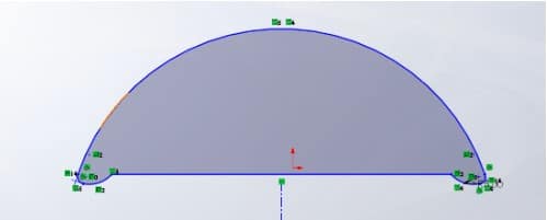
The diameters of these D-shape tubings range from 34x12x1.5mm to 178x58x3mm. The first easy approach involves drawing a d profile, which is then extruded or turned into a sweep boss. I will thus create a d drawing similar to the one shown below. Use the measurements that are appropriate for your needs.
Exit the sketch mode. I’ll draw another sketch to serve as the path for my sweep boss. In this case, I’ll just draw a straight line. Next, I’ll start the sweep boss command. I’ll select my profile and the straight line as my path. The thin feature option will also be checked.
For my thickness, I’m going to use 5 mm. Depending on your design requirements, you can choose to add material in an inner or outer direction.
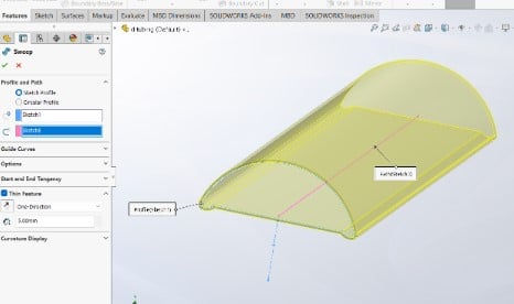
After entering the necessary settings, click the green checkmark to execute the sweep boss command. The alternative approach consists of just making a boss extrusion of the profile and a cut extrusion to create the hollow.
The typical library does not have the D shape tubing. The subsequent sections provide a straightforward method for routing common components.
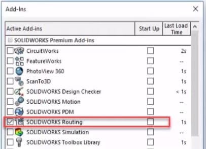
Activating The SOLIDWORKS Routing Add-in
Select SOLIDWORKS Routing from the Active side by checking the box under Tools > Add-ins. The Routing add-in will load when SOLIDWORKS is launched if the Start-Up side box is checked.
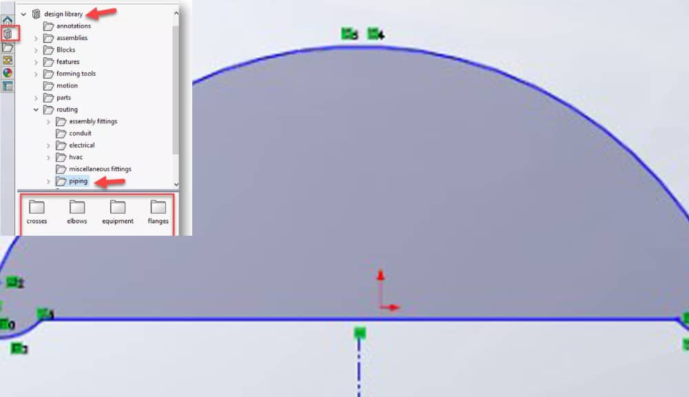
Using the Routing Design Library
The SOLIDWORKS Task Pane contains the SOLIDWORKS Design Library. The Routing subfolder may be seen by expanding the Design Library folder. The Piping folder, which is underneath the Routing folder, contains all the elements required to build the Piping Route.
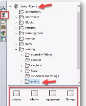
NB: If the Design Library is not visible, navigate to Tools > Options > System Options > File locations > Routing and press the Add button. The Design Library’s default location is C\ProgramData\SOLIDWORKS\SOLIDWORKS 20XX\Design Library.
Starting a pipe route
- Opening a new assembly in SOLIDWORKS will be the first step in this lesson.
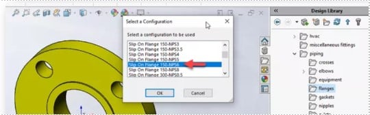
- Then, in the Design Library, navigate to the Piping folder and then the Flanges folder.
- Drag the slip-on welding flange from the Design Library to the assembly’s origin.
- Click OK after choosing the Slip On Flange 150-NPS6 arrangement.
- The Design Manager Feature Tree then shows the Route Property Manager once you click OK.
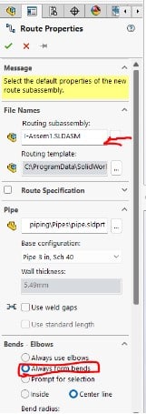
Overview of the Route PropertyManager
- The nomenclature for the Routing Subassembly that will be developed is displayed under File Names > Routing Subassembly.
- You may add a space between components by choosing Use Weld Gaps under the Pipe Category.
- By selecting this option, the pipe will be cut into lengths that are typically bought. The pipe will be divided into 20-foot portions if you purchase it in 20-foot lengths.
- Set the Always Use Elbows option under Bends – Elbows.
- To find the component, click the browse button. In the Route PropertyManager, choose OK.