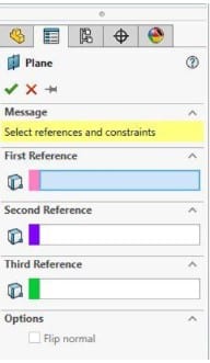
Each Part and Assembly file in SolidWorks by default has a Top, Front, and Right plane. Despite having screen bounds for viewing and selecting, each plane is unbounded. The modeling process can be facilitated by adding more planes.
Up to three references can be chosen to define a plane. You have the option of choosing a vertex, point, edge, or face. Similar to how dimensions are regulated on a blueprint, they are under the control of geometric restrictions.
Additionally, planes can be rotated a certain number of degrees or displaced by a certain amount in relation to your choice. This article examines the creation of planes and the appropriate references.
Ways How to Create a Plane in Solidworks
Start by clicking the tab for your features. Select “Plane” from the drop-down menu under “Reference Geometry”.
The manager for creating your planes will appear on the left. The controls you may use to control the plane will also be shown there, along with the references that appear when you pick them.
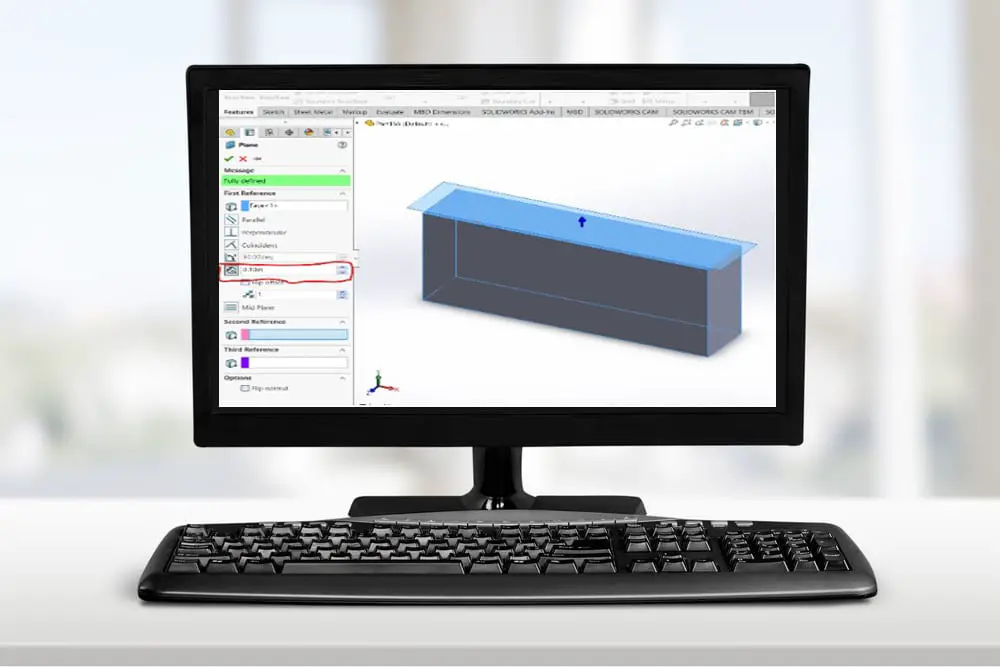
Creating offset planes
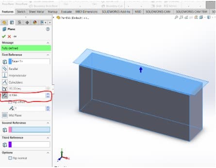
A plane that is offset is the most typical kind of reference plane. Use the CommandManager’s Reference Geometry drop-down menu to choose the Plane option to construct an offset plane. Choose a face or another plane and enter an offset distance once the option to build a plane is active.
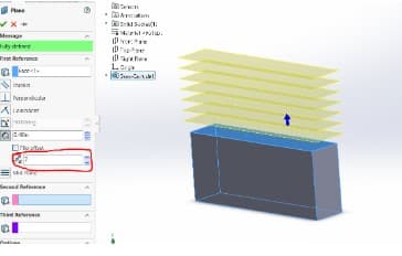
Generating an offset plane also gives you the option of making several planes. This method of constructing several planes results in all of the produced planes having the same offset from one another.
NB: As soon as you choose a face, you’ll notice that the message on the left side changes from “Select references and constraints” to “Fully defined.” The following principle, which also applies to drawings, must always be followed while making planes: A plane has to be completely defined.
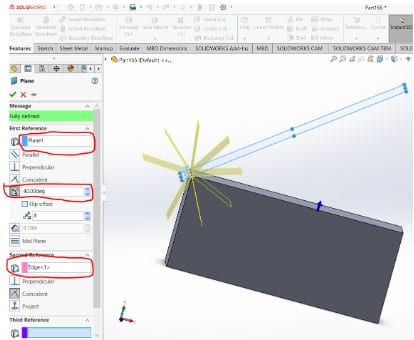
Creating Planes at an Angle
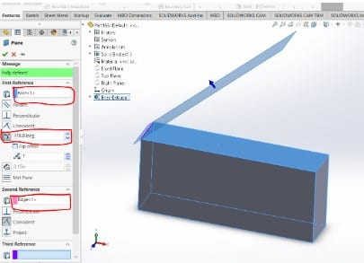
You’ll need a face and an axis line to angle about in order to make an angle plane. An edge from a model or a drawing may serve as the axis line. You can alter the angle at which the new plane is offset from the chosen face. By default, it will be perpendicular to the chosen face/plane.
It is possible to simultaneously generate a number of angle planes, each with a different angle from the previous one.
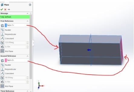
Generating Mid Planes
By default, a mid-plane is made when two faces are chosen. There is no need that the chosen faces be parallel. The resultant plane will be parallel to and halfway between them if they are parallel. Otherwise, the plane will be placed in the middle of the two faces. This kind of plane is frequently used to make a mirror plane at the part’s center.
Creating planes that are Coincidental
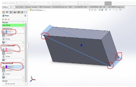
- Using points
Picking three or two points on your model will create a Coincident plane. SOLIDWORKS will provide a plane that connects all three points at whichever coordinates you choose. This is one of the few plane types where you must utilize all three options for the reference point in the feature tree in order to specify the plan completely.
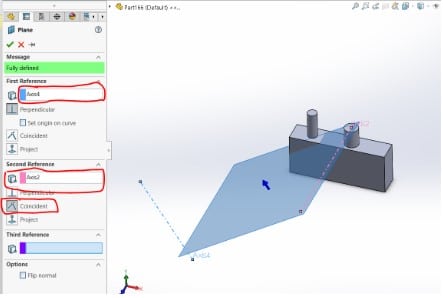
- A two-axis-defined plane
There are instances when you have to make a plane that passes through two axes. Make sure the axis you intend to utilize is visible first.
Select one of the axes as the First Reference, and the other axes as the Second Reference. Choose Coincidence in both situations. Once the green checkmark is clicked, a new plane will be constructed.
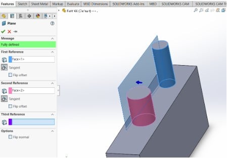
Creating Planes on Cylindrical Surfaces
The complexity of planes on cylindrical surfaces arises from the fact that additional options are frequently required in order to complete the plane.
If a cylinder and a plane are chosen, for instance, the plane will revolve around the cylinder’s face when the angle is changed. Alternatively, a plane that is tangent to both cylinders will be added if more than one cylindrical face is chosen.


