
Mechanical springs, including coil, leaf, volute, and compression springs, are elastic objects that store mechanical potential energy when deformed by compression, extension, or torsion. When an external force is applied, the object changes shape, and when the force is withdrawn, the object resumes its original shape.
When the spring reverts to its former shape, the energy that was absorbed is restored and stored in the spring. So, how does one create a spiral or spring in SOLIDWORKS? Therefore, we’ll go through how to create a spiral spring in Solidworks in this article.
Methods on How to Make a Spring in Solidworks
First method
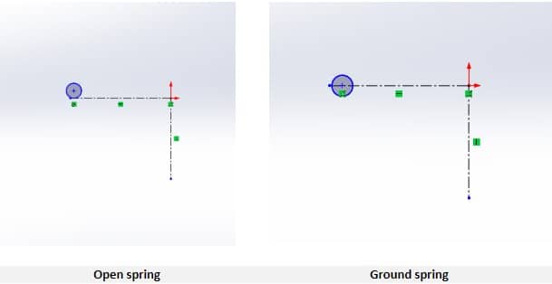
Make a wire sketch on the front plane to get things going. To locate the wire circle, draw sketch lines. Set the spring’s diameter to meet your needs. Make sure the center, outside, or inner diameter is adjusted according to your preferences.
The bottom tangent of the wire circle should be connected with the center line for the spring diameter (your spring’s cross-section) in the case of an open spring. It is to the middle of the circle (the cross-section of your spring) for the ground spring.
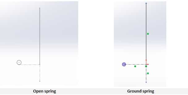
A construction line should be added to a new sketch on the front plane. For the purpose of creating the appropriate dynamic spring, this line should not be fully defined. A perpendicular line with a length equal to the inside diameter of the wire circle should be present at the top of the construction line for an open spring.
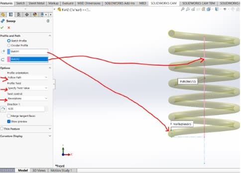
Once you’ve finished this drawing, select “Swept Boss/Base” from the features menu. In the features tab, after creating this drawing, select “Swept Boss/Base”. The path should be the line, and the circle should serve as the profile.
Choose twist along the path as the orientation/twist type and define by turns in the sweep feature’s choices. Then, choose the number of turns to define by, click the green check, and you’ve got a spring.
NB: These sweep options should be used for both types of springs
Second method
The helix will be used in this technique to make the spring. Choose the Top Plane from the feature tree’s menu on the left, then click SOLIDWORKS 2D Sketch to start a sketch. The top plane now faces you when the display changes.
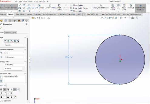
Select Circle from the Tools menu, or just click the Circle symbol. Make a sketch that begins at the Origin. By selecting the “dimension” option, you may change the circle’s diameter to 80 mm.
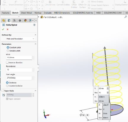
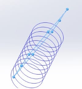
- Choose “Insert”, then “Curve”, “Helix/Spiral”, or simply click the Helix/Spiral icon.
- Pick to use Constant Pitch.
- Determine a suitable Pitch length based on your requirements.
- Choose your own number of revolutions based on your requirements.
- You should adjust the Start angle to suit your needs.
- Depending on your requirements, choose either the clockwise or counterclockwise option.
- Then click OK (the green check mark).
Next, construct a plane perpendicular to one of the helix’s ends.
On the plane’s origin, draw a circle with a diameter equal to your spring’s cross-section.
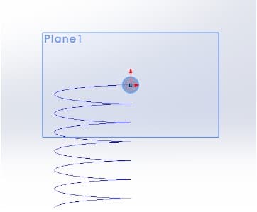
Now exit the sketch mode.
Go to Features. Then, choose Swept Boss/Base, Sketch2 as the profile by clicking on the circular sketch, and Helix as the path. Then click OK (the green check mark). Congratulations—your personal Spring is now complete!
Inserting a Top Flat End
For a ground spring, you might want to add flat ends. Pick the second drawing. Make a plane that is parallel to the spring’s centerline. The top plane should be parallel to this. These planes will indicate where the flat ends of your ground springs will be trimmed off.
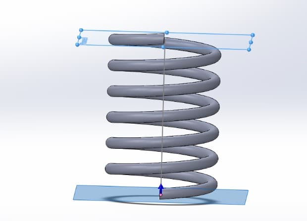
Choose the plane from the spring’s top. Then use the SurfaceCut option to insert a cut into the material. Ensure that the cut is directed away from the spring. For the bottom flat end, repeat the process. Your ground spring is now ready to be incorporated into an assembly design.