Any entity in a component file or assembly may be rotated or moved with the help of SolidWorks’ tools. In a part file, you may need to rotate or move any sketch entities, but in an assembly file, you may require a move or rotate tool when adding or mating a component.
The procedures required to accomplish the rotate operation in SolidWorks will be made clear to you in this article.
Easy Ways on How to Rotate in Solidworks
Rotating a Drawing View
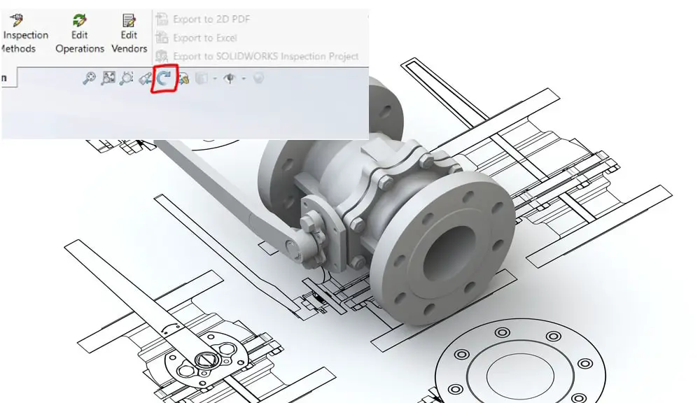
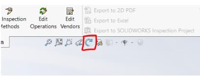
A Rotate View Tool is indicated in yellow in the tool palette seen below. You may rotate a single view or all of your views at once with this tool. You can only rotate the view(s) on the plane that they are on using this approach, but you may do it in whatever increment you choose.
Upon selecting the Rotate View Tool, the following pop-up dialog box appears:
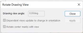
Everything is grayed out since we haven’t chosen a view. All of the perspectives will rotate together if you choose the main view. Uncheck the box next to “Dependent views update to change in orientation” if you just wish to rotate one View at a time.
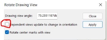
To make those changes, be sure to click Apply.
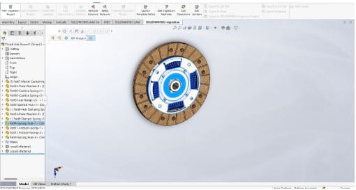
Rotating an assembly or part
The wheel serves as a button, to begin with. The model revolves around a face I’ve selected in my model using the wheel, which I then click and move. With an edge, I can accomplish the same. I can now get my model to pivot on the edge I’ve picked by selecting that edge and clicking the wheel.
This is a terrific approach to move a piece of equipment so you can see it from the best perspective. Rotate About the Scene Floor is an additional hidden parameter that may be enabled for components and assemblies.
As a result, the rotate function behaves in a somewhat different way, and it also makes a fantastic presentation tool for showing off designs.
The ability to move and drag a second part within an assembly by clicking and dragging it with the left mouse icon is something I’d like to draw attention to as it is not a feature of the rotate command.
The right mouse button may now be used to click and hold down to rotate that component independently of the other parts of the assembly.
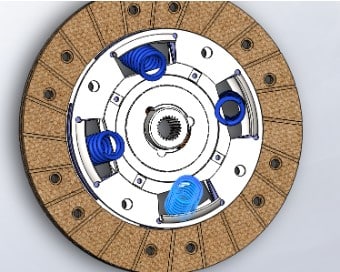
As an illustration, I simply rotated the damper springs by right-clicking and dragging them.
Rotating Text
SolidWorks supports rotating text. Depending on whether you are modifying a drawing or a part or assembly, there are several alternatives available.
The CommandManager’s sketch tab has a button called “Text” that you may use to add text to sketches. Using “Text,” which is accessible via the CommandManager’s sketch tab, you may add text to drawings. Choose an edge, curve, or sketch object when inserting text to make the alignment choices available.
The text will follow the arc’s path if an arc is chosen. By altering the start and finish points of the arc, the text may be rotated.
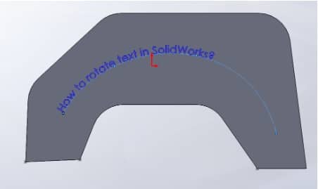
An edge or line may be used in place of an arc. If a line is employed, change the angle as needed. By altering the angle value, the text in the image below is rotated. The possibilities for alignment are grayed out in the absence of the line.

Rotating words or individual letters is also an option. To do this, pick the text and click the rotate symbol as seen below. Use the syntax r45 before and r after the word or letter that has to be rotated. The rotational angle is represented by the number.
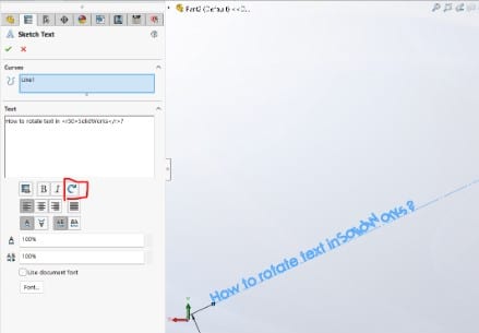
For this example, Solidworks is chosen and rotated by 30 degrees. If blocks are utilized, they can be rotated. Choose the block to be rotated, uncheck “Lock angle,” and enter a value. It should be noted that this rotates the entire block, not just the text; if the block merely includes text, there won’t be any problems.