Scaling is a technique that enables the measurements of a part to be altered all at once by a single factor rather than altering each one individually. Scaling may be applied to increase clearance, allow for thermal expansion, change units, or address the situation when there are several instances of the same item in various sizes.
Figuring Out How to Scale Parts in Solidworks
In SOLIDWORKS, there are two methods for scaling a part:
- Scale Tool
- Using a Design Table
Using the Scale Tool
Utilizing the Insert, Features, and Scale buttons will give you access to the Scale tool.
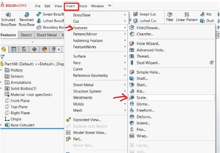
By doing this, you may access the Scale Component dialogue box and choose the part’s scaling factor.
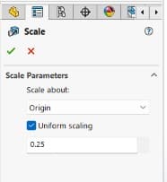
The part will be scaled using the selected scaling factor after the required scaling factor has been entered and the “OK” button has been clicked. There are three options available once the Scale feature has been selected for scaling: Scale about, Uniform scaling, and the scale.
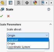
- Scale about
The Scale about option specifies the position where the scale will begin. Scale about option. On each axis, the scale is applied to both directions.
Three alternatives are available when deciding where to scale about: centroid, coordinate system, and origin. By using the drop-down arrow, as illustrated below, you may view these choices.
When a part is scaled about its centroid, its dimensions are evenly increased or decreased in the X, Y, and Z directions around the centroid. This is helpful if the position of the part is not important once the scaling has been done.
When the position of the component after the scale feature has to be known, scaling around the origin is beneficial since it modifies the part’s dimensions by utilizing the origin as the beginning point. This may be applied in a scenario where the origin of the scaled component is mated in an assembly to another part.
The process of scaling about a coordinate system is identical to scaling about the origin, with the exception that the user-defined coordinate system is used. This decision will be based on whether the part’s position is still relevant after the scaling feature has been implemented.
- Scale Uniformly
Scale uniformly would either be enabled or disabled. When left unchecked, this enables the part to be scaled in the X, Y, and Z directions at various rates. If the part has to be grown taller but not broader or deeper, this might be useful.
This might be applied in a scenario where the same component, such as a support or dowel rod, has many functions yet comes in various sizes. If there are three supports and the length is the only variable, make one and scale it to the other sizes, then save it as a separate part file.
This may save a lot of time because only one model needs to be made, and two features can then be added. Below is a screenshot of this menu.
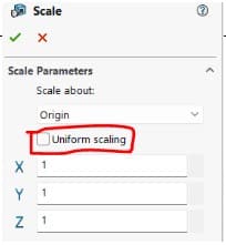
The value to be multiplied by the initial dimension is the scale. The scale would be 2 if the part required a double increase in size. Scale values range from 0 to 10000000000. When you’ve decided which ones to pick, finish the scale by clicking the green checkmark.
Using a Design Table
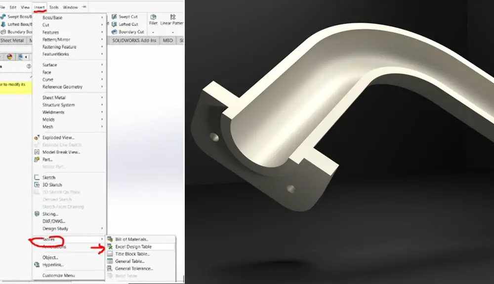
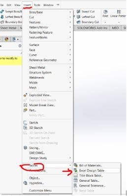
Access the design table by selecting Insert > Tables > Design Table.
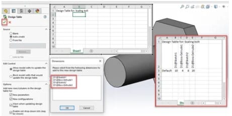
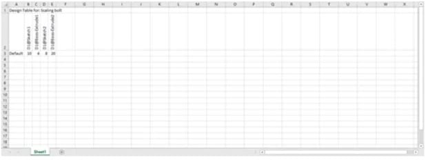
I’ll pick Auto-create and leave everything at its default settings; a popup will appear where I can choose the dimensions, I want to be included in the design table. I’ll pick them all. The table will be produced using SOLIDWORKS.
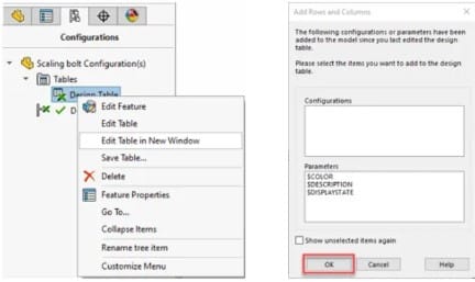
By choosing the Configuration Tab, opening Tables, and right-clicking the Design Table in Excel, I can update it without using the user interface. the option to Edit Table in New Window.
When the Excel window opens, I’m prompted to choose elements that have changed since the last adjustment. After choosing OK, the table is shown in its entirety in Excel.
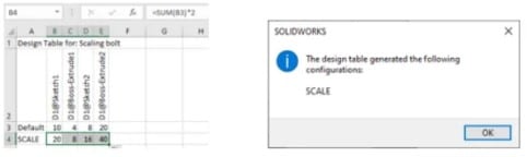
The next step is to establish a new configuration by giving it a name and adding a scale equation (= dim * 3), which triples the configuration’s overall size and propagates it to all of the model’s dims. Excel should be saved and then closed. The updated configuration is shown via a message. Hit OK.
The drawing that was previously shown as “25” dim will now display as “50” if I switch the component configuration to the new SCALE setup.