The presentation of a Cosmetic thread can be impacted by several factors. Depending on the component, feature, and even the environment you’re working in, each of your SOLIDWORKS parts, assemblies, or drawings will appear differently.
This guide will take you through all of the potential causes and demonstrate a permanent solution to your Cosmetic Thread problem. Before we get started, let’s look at a few benefits of cosmetic threads.
Benefits of Cosmetic Threads
A suggested best practice to represent threads in your models and lessen the effect on performance is to use cosmetic threads. It is usually better to utilize cosmetic threads with imported or non-SOLIDWORKS native parts. They also make it simple to annotate lines on a drawing.
In SOLIDWORKS, there are several ways to display them. They can be formed when using the Hole Wizard feature, displayed on Toolbox fasteners, shown on tapped holes made with the Hole Wizard tool, manually inserted into any circular boss or hole using the Cosmetic Thread feature, and displayed on tapped holes created with the Hole Wizard feature.
Without Cosmetic Threads, it could have been difficult to include a thread call-out to indicate that one is being used in a component or design. Now you can do so quickly. For those who want to shorten build times, cosmetic threads are perfect.
Multiple triangles are not made since Cosmetic Threads is not a helix but a visual picture. It can strain the graphics hardware in the server and create downtime to display these triangles as different geometries in a small, circular sweep shape.
How to Fix Solidworks Cosmetic Thread Not Showing Problem
Causes and remedies for missing cosmetic threads
- The options that may be useful if you find that your cosmetic thread is missing are outlined below. We will investigate the part, assembly, and drawing environments separately.
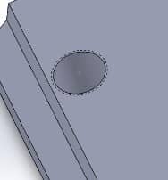
It appears as a dashed line around the hole when the functionality is enabled, as illustrated in the image below.
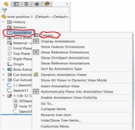
If you want a visual depiction of the threads on the hole face, you may right-click the Annotations folder in the Design Tree and choose Details.
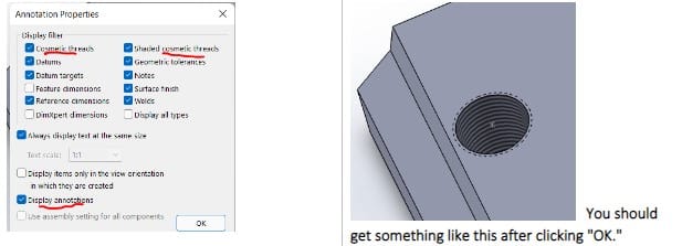
Make sure “Cosmetic threads,” “shaded cosmetic thread,” and “Display annotations” are all chosen in the Detailing section.
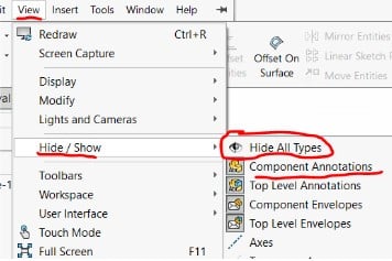
The “annotations” may be set to “hidden” if all of your settings are correct but you still can’t view your cosmetic threads. Navigate to Hide/Show under View to verify that.
Make sure that “Hide All Types” is not chosen (depressed) and that “All Annotations” is. All annotations, including your cosmetic threads, will be displayed.
- As you work in the assembly environment, first check to see that the cosmetic threads are first displayed in the part environment, as stated in the section above. Then choose the View tab and go to Hide/Show. Make sure that “Hide All Types” is deselected and “Component Annotations” is selected.
In a manner similar to how we checked the part-level properties earlier, we now verify the document properties. ‘Cosmetic threads’ and ‘Display assembly annotations’ should both be selected.
Once more, these options from the Document Properties are related to those from the Annotation Properties. Right-click the Annotations folder in the Design Tree and choose Details.
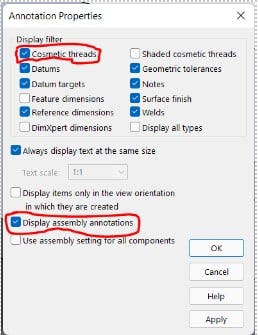
NB: There are a few things to look for if the cosmetic threads were applied at the part level but do not appear at the assembly level. The cosmetic threads won’t appear in the assembly file if “Display assembly annotations” is deselected and “Use assembly setting for all components” is chosen. Deselect “Use assembly setting for all components” to make sure both are chosen.
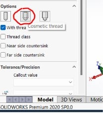
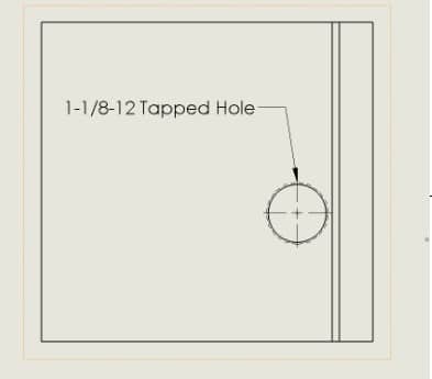
- When it comes to cosmetic threads being displayed in drawings, callouts are automatically added to drawing views of Part files that include them by default. That is, assuming the Hole Wizard feature’s hole callout option was used. The drawing will look as depicted below.
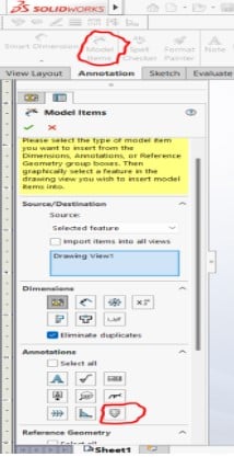
In contrast to part models, assembly model views will require manual input. You may accomplish this by selecting “Model Items” from the Annotations menu.
Next, choose a view; a section titled “Destination view(s)” with the chosen view will then display. Next, choose the cosmetic thread icon under the heading “Annotations” (as shown in the picture below).