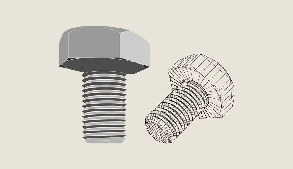
Understanding the many ways to add threads in SolidWorks, as well as the benefits and drawbacks of each approach, is crucial before applying threads. This article explains how to apply threads in Solidworks and how to select the best way.
In SolidWorks, cosmetic and model geometry threads are the two primary forms of thread that may be used. The first decision to be made is which of these approaches is best for your application. Cosmetic threads are categorized as annotations.
They do not require thread modeling since they represent the characteristics of a hole or an external thread. Cosmetic threads are lightweight and do not increase the model’s rebuild time because they are annotations and do not contribute to model geometry.
Cosmetic threads may be introduced either manually or automatically as part of a hole wizard, hole series, or other function. Model geometry threads cannot be applied to a model using a particular “thread” feature. A sweep function is most frequently used to remove material from or add material to the model.
Model geometry threads will dramatically lengthen model rebuild times and use more machine resources than cosmetic threads. When the component being modeled needs a thread as part of the tooling process, model geometry threads should be employed.
Techniques in Solidworks on How to Make Threads
Utilizing the Integrated Thread Feature
The built-in thread functionality makes it simple to model a thread if you want something a little more precise. This is a nice method for modeling that requires little effort and is somewhat realistic.
If you merely need a thread that functions or if you want to utilize it as a starting point for custom modeling, you might choose to adopt this approach.
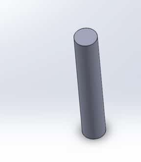
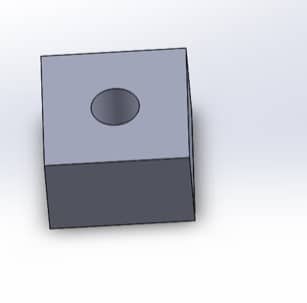
- Start by producing a cylindrical extrusion or hole. Choose the beginning edge from there.
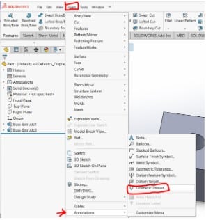
- After that, select “Insert,” “Feature,” and “Thread”.
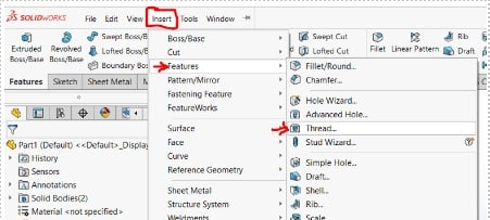
A thread will be automatically started by this. The termination condition, size, and different thread standards can all be specified. Just play around with these parameters until you achieve your desired results.
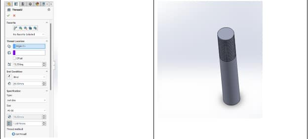
You’ve now successfully modeled threads in Solidworks. This function is virtually as quick and simple to use as establishing a cosmetic thread. It provides a fantastic balance between speed and precision.
Creating Cosmetic Threads
Cosmetic threads could be adequate for you, depending on your demands. These offer the look of threads as a “skin” applied to other aspects of your model but are not precisely designed to meet your technical requirements.
It may not be necessary to have an identical reproduction in the Solidworks mockup if you are developing a product and know you will utilize a stock fastener. For draft designs, this is especially true.
To make cosmetic threads, follow these steps:
- Create either a cylindrical hole or a cylindrical extrusion to serve as the male thread first (for the female thread).
- Next, choose the edge from where the thread will emerge.
- Click “Insert,” “Annotations,” and then “Cosmetic Thread” to finish. You will have the chance to specify the thread class, size, and end conditions at this point.
Custom Thread Modeling
Model the main shape first up until the thread addition. Both the component with the male thread and the component with the female thread should be modeled.
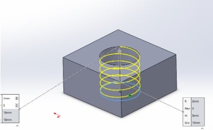
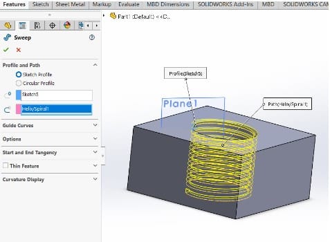
Then decide where the thread will begin from on the edge. Construct a circle whose main diameter equals the thread. Click “Insert >Curve > Helix > spiral,” and then “Next.” For the thread length and pitch, respectively, define the helix’s height and pitch. Ensure the proper twist is achieved as well.
The normal direction of a right-hand thread is clockwise, while a left-hand thread is typically counterclockwise.
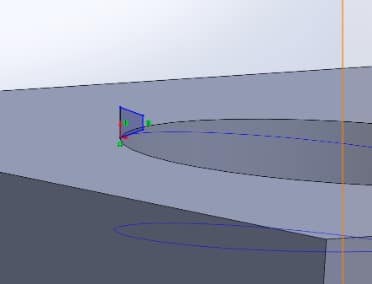
The thread teeth profile will then be defined in the plane perpendicular to the thread route. Based on the screw pitch, minor diameter, thread angle, and other necessary dimensions, this should be done. To calculate the thread profile for your fastener, you can use specifications like ASME/ANSI 81 or ISO 965-1.
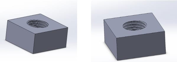
Then, to build your custom thread, do a sweep or swept cut. You have modeled it at this stage, and you’re practically done.
Cleaning up part of your work is the last stage. Any extra surfaces should be removed by extruding or cutting.
Tip
Remember, too, that a complicated thread will result in a bigger file and a longer rebuilding process. The most compressed files will be produced using technique two, then using method one, then method three. Because of this, think twice before employing custom modeling even if it might provide you a lot of creative freedom.