Operation failed due to geometric condition is a frequent error that can arise during the design phase (when working with improper geometry).
There are several reasons that might lead to this error. In this article, I’ll explain how to handle “geometric condition error” or “zero thickness error.” These two terms simply denote the same thing.
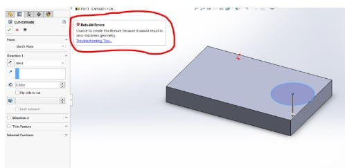
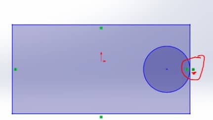
Let me demonstrate what I mean when I say they both relate to the same thing. I’m going to extrude a rectangle after modeling one with a tangential circle within.
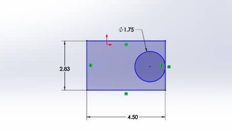
Nothing appears to be wrong. The center part will now be extruded, but without the hole.
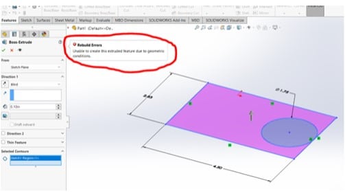
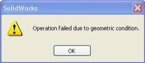
After clicking the green check mark, the error “unable to generate the extruded feature due to geometric condition” appears.
I’ll draw the identical rectangle and then extrude it to demonstrate the zero-thickness error. Then I’ll draw a tangential circle on one of the rectangle’s extruded faces and make an extruded cut of the circle.
After clicking the green check mark, it displays a zero-thickness error.
Factors that contribute to geometric condition error and/or zero thickness error
When edges or vertices in a solid model do not correctly link with neighboring geometry, zero-thickness geometry is created. A solid geometry that contacts itself at a point or an edge is known as a zero-thickness geometry. A solid body must have precisely two neighboring faces on each of its edges.
Although other CAD programs permit this, SolidWorks does not since it might result in mathematical issues and unexpected inaccuracies in the model as you work. Furthermore, a component with Zero Thickness Geometry cannot be produced in a single piece.
Geometry errors are caused by the following types of geometry:
- Corners of sheet metal that only contact on one edge or vertex
- Cylindrical surface with tangent
- Helixes/springs with pitch equal to wire diameter
- Tangency to surfaces that appear to be planes or cylinders but are not because they are lofted B-surfaces
Fixing the Solidworks Operation Failed Due to Geometric Condition Error
Fixing the geometry condition/Zero Thickness Error
- In order to effectively connect the edges and vertices of the geometry with zero thickness, add or remove enough solid material from the surrounding region.
- Clear the Merge Result option in Direction in the PropertyManager when adding the feature, if it’s an option. A multibody component is produced as a result.
How can I troubleshoot geometry condition errors and zero thickness geometry?
- Always include all required dimensions and relationships in a drawing. The best method to work is with fully defined sketches, however, this is not always required. Sometimes a line appears to be horizontal, but if it doesn’t have a horizontal relationship, there is a chance that it is actually at a very small angle, say 0.001 degrees, which you can’t see by simply looking at it.
- If you get this error when using the Cut feature, look for the entities (such as lines, arcs, splines, etc.) that are close to the edge and have a tangent relation applied to them. Remove the tangent relationship and relocate the object just a tiny bit. Additionally, this technique is effective for splits that fail due to zero-thickness geometries.
- If you get this issue when using Section Views, attempt to move the section line or plane slightly. In most cases, it resolves the issue.
- It is advised (unless you are an expert) not to erase their relations if you use Convert entities or Silhouette entities to convert an edge or another object because doing so might result in Zero Thickness Errors.
- If everything else fails, the problematic feature can be one that you previously built but that SolidWorks permitted despite having faults. Under the Performance menu on the System Options Tab of Settings, you will discover Verification on Rebuild.
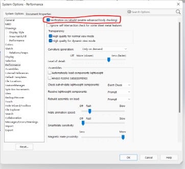
SolidWorks verifies every new or modified feature it builds against every face already present in the model when this option is enabled, rather than just the adjacent ones as it does when it is inactive. This guarantees that your model is free of flawed geometry.
However, this option is disabled by default since it reduces performance, particularly for large, complex models with several faces. Rebuild the complete model by pressing Ctrl+Q on your keyboard after checking this option and clicking Ok to save the settings.
If any faults or warnings were discovered in the previously generated features after the rebuild, SolidWorks will notify you of them.