Instead of attempting to predict the project’s shape while developing anything in SOLIDWORKS, it is frequently helpful to import a basic notion of the project in the form of a 2D picture and then trace over it. However, there are situations when you wish to use the sketch picture tool and it is grayed out.
This post will cover the reasons for the grey-out problem, how to solve it, and how to insert a sketch picture appropriately.
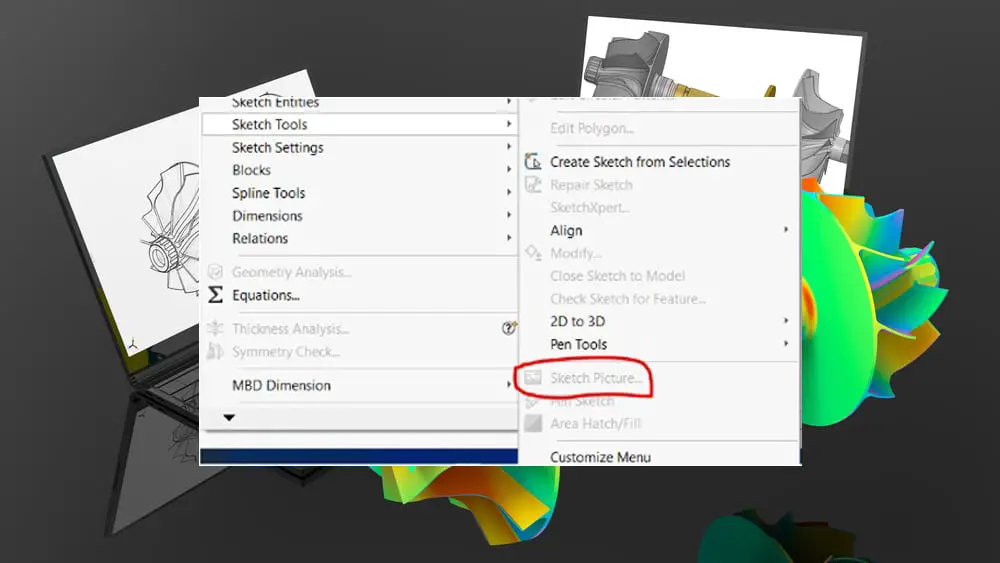
Possible causes of a greyed-out sketch picture
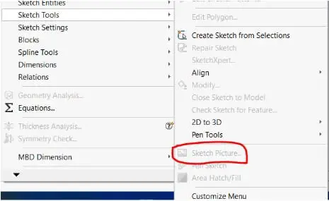
The major cause of the command Sketch Picture being greyed out is that you are not currently in sketch mode.
As a result, you must first verify that you are in Edit Sketch mode by either starting a new sketch or editing an existing one. The command Sketch Picture may be found under Tools > Sketch Tools > Sketch Picture.
Troubleshooting Solidworks Sketch Picture Greyed Out
How to properly insert a sketch picture
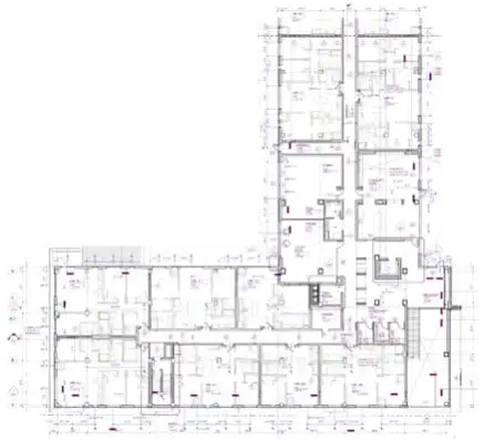
There are several file types supported, including.jpg,.tif, and .bmp to mention a few. In this illustration, we’ll use a picture of a building’s floor plan as our model.
We begin a new sketch and use the “Sketch Picture” command to add the picture. Using the “Sketch Picture” command, we begin a new sketch and add the image. The command may be accessed by using the pulldown menus at Tools > Sketch Tools > Sketch Picture.
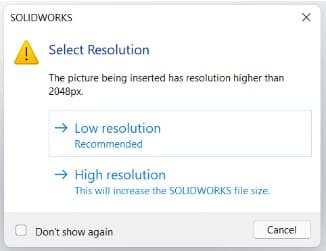
When you choose your image, a select resolution dialogue box will appear, asking you to choose a resolution type. Depending on how well your computer performs, you can select either high or low.
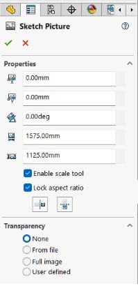
After the picture has been placed on the sketch plane, the Sketch Picture properties will appear in the Property Manager on the left side of your SOLIDWORKS screen.
The X, Y, angle and overall width and height values of your image are all controlled by these parameters. Be aware that these values only affect the size of the entire image and do not serve as a reference for the image’s geometry.
Additional options include locking and unlocking the aspect ratio, turning your image horizontally or vertically, and enabling or disabling the scale tool.
The picture must then be scaled and positioned. In this example, we’ll begin by dragging our image to the sketch origin by clicking and dragging it anywhere on the sketch picture. To utilize the scale tool, you must drag the line’s and the arrow’s beginning points to a predetermined spot on your picture.
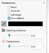
Additionally, you may make any white area in your image translucent by choosing User Defined under Transparency and choosing the white pixel color by hand using the color palette dropper option.
Using the scale tool is a simple approach to sizing it. A blue line is shown on the image when the scale tool is selected.
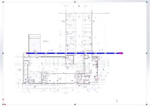
Drag the scale tool’s left end (pink circle) to a start point and the right end (pink arrow) to an end position. A dimension dialog box will show up as soon as you drop the arrow location.
Enter the known distance into the prompt after entering it. Your provided dimension value will determine whether the image is scaled up or down.
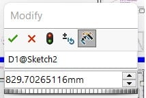
It is possible to check if a picture was scaled successfully by drawing a construction line over it and adding a Smart Dimension.
NB: Make sure the sketch picture is the only item in the sketch if you want to use it for tracing, and then create a new sketch for your tracing geometry. This will be useful in the event that you ever need to conceal or suppress the original sketch image without also hiding or suppressing the traced sketch geometry.