We’ll learn how to use surface modeling tools in this SOLIDWORKS course. If you have experience with complex surface modeling, you may create free forms using the SolidWorks application.
By the end of this SOLIDWORKS welding helmet modeling tutorial, you’ll have a firm grasp of how to utilize various surfacing tools.
Methods of Welding Helmet Drawing Solidworks
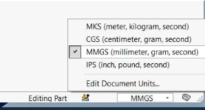
We’ll start by opening SolidWorks. Confirm that you are using metric units. Verify by clicking on the MMGS option in the lower right corner.
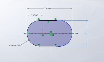
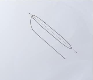
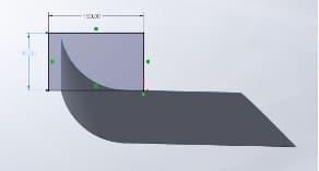
Then enter sketch mode. We will begin by drawing three sketches that will be used with our surfacing tools. These three drawings are for the main frame. So for our initial sketch, we’ll use the top plane. The initial sketch must resemble a straight slot, such as the one seen below.
Exit the first sketch. We then proceed to sketch the second sketch. Right-click on the front plane and pick the sketch symbol. Then click the standard icon.
![]()
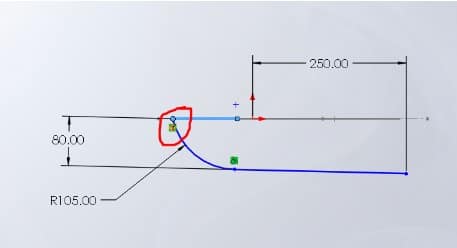
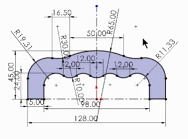
The second sketch will be similar to the one below. The second sketch pierces the first sketch in the location indicated on the illustration below. Use the dimensions provided, and only those.
Exit the sketch mode. After the first two drawings, your drawing should resemble the one seen below. These two sketches are perpendicular to one other.
The third drawing will now be shown. Right-click on the right plane to select Sketch.
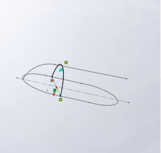
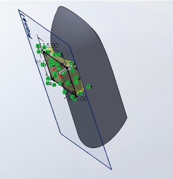
Similar to the arcs that were previously employed, the third sketch, is a three-point arc. The first arc is pierced at two points by the end points of this third arc. Its center pierces the second arc as well. Ensure that it will resemble the example in the figure below.
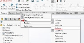
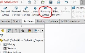
Exit the sketch mode. We’ve moved on to the surface tab. If you don’t see your surfaces tab, right-click on the sketch tab and select Tabs. Then choose surfaces.
Left-click the Boundary Surface on the surface tab.
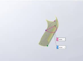
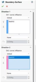
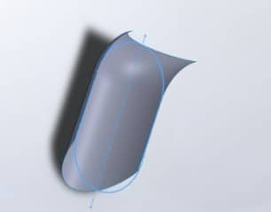
The boundary surface tree manager will be displayed. Select sketch two under the first direction, and sketch three under the second direction. These options will result in a preview similar to the one shown below.
Also, confirm that your boundary surface settings are similar to those in the illustration below.
Click the green checkmark to exit the boundary surface mode. Trimming the surface is the next stage.
The first sketch will serve as our trimming tool. Click the trim icon under the surface tab to trim the surface. You may choose between “Keep Selections” or “Remove Selections” in the trim tree manager. Select the first drawing to use as a trimming tool.
Your decision to remove or keep certain pieces on the surface determines the portions you choose. After this trim, the surface will have the desired bottom edge.
We then create a second drawing to trim the top and get rid of the horn-like surface. Here, I’m going to utilize a rectangle as my trimming tool. After generating the trimming sketch, carry out the trimming procedure as we did in the previous trim.
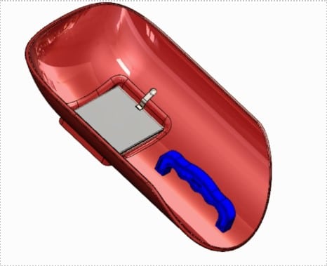
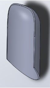
You may also add a 3mm mid-thickness to it after the trim process. The final product will resemble the component below.
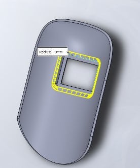
The front of our helmet will now have an opening cut out of it. In order to begin, we will first offset the top plane to the front of the helmet by 95 millimeters. A rectangle is then drawn and extruded. After that, give the corners of the rectangle a fillet radius of 10 mm.
Next, add a 90 by 70 mm rectangle to the original extruded rectangle. The front opening is then created by cutting an extrusion.
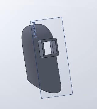
The extruded rectangle is then modified to have a 3 mm thickness. The inside edges are then given a fillet, as seen in the picture below. These are for the welder’s safety.
The modeling of various accessories, such as the black glass for the helmet opening, comes next once the primary frame has been modeled. This rectangle is 105 mm by 85 mm. After that, we will extrude it by 3mm.
We’ll also create the handle by making a 15mm mid-plane extrusion of the sketch below.
We then assemble our helmet after modeling all of the components.