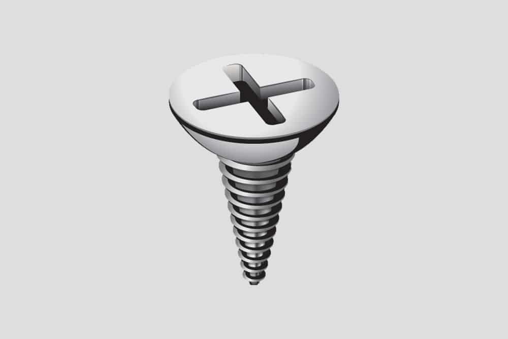
In this tutorial, we’ll use SolidWorks to design a screw. As you probably already know, screws are crucial small parts that keep things from collapsing.
Easy Ways How to Make a Screw in Solidworks
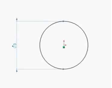
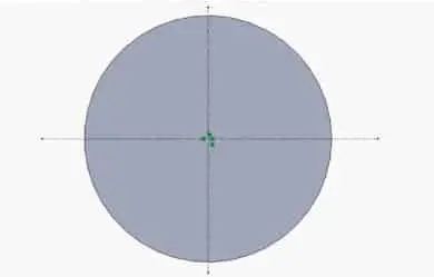
We’ll launch SolidWorks. Make sure you’re using metric measurements. Verify by selecting MMGS in the lower right corner. Next, go to sketch mode. We’ll start by sketching a circle. So, we’ll use the front plane in our first sketch. Initially, we will draw a circle starting at the origin. The circle should have a 3 mm diameter.
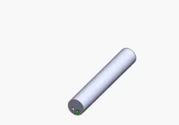
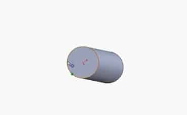
Then click the command tab and choose features. Next, we choose “extruded boss” under features. Hit the green checkmark after entering an extrusion length of 19.5mm. This will result in a uniform cylinder like the one in the illustration below.
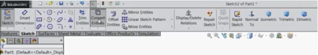
Next, choose whichever of the cylinder’s two faces you want. Right-click and begin drawing. Afterward, choose “Convert Entities”. As illustrated below, the sketch tab is where you may access the “convert entities”.
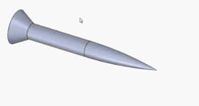
The cylinder’s edge has now been conveyed as a circle sketch. Select “extruded boss” after that, and give it a 7mm length. Additionally, pick a 12-degree draft angle. You will receive a feature similar to the one below as a result.
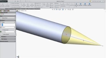
To continue, click the green checkmark. The outcome will be the same as the one displayed here.
Next, choose the opposite end face of the initial cylinder. Right-click and choose Sketch. Then select convert entities once again. It’s comparable to what we did previously. This will result in another circular drawing.
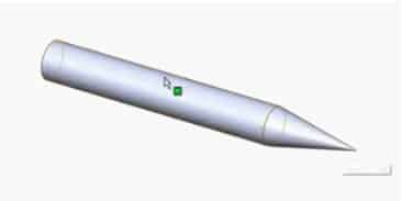
Then choose extruded boss. A 3mm extrusion length and a 30-degree outer draft angle should be used. Next, click okay.
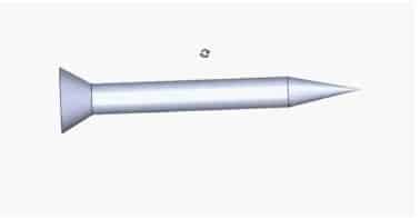
At this moment, we have a formed screw shape. The next step is to give one of the edges a fillet, as indicated in the picture below. It receives a 68mm fillet radius. Then click OK.
Making a screwdriver groove
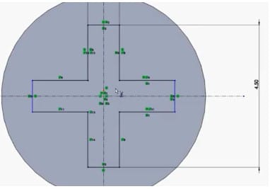
Next, choose the top of the screw’s head. Right-click and choose Sketch. Next, pick the centerline. As seen below, draw a horizontal line through the origin. Another vertical line through the origin should be drawn once again.
Next, we choose a corner rectangle. Next, as seen below, we create two rectangles that are perpendicular to one another.
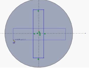
Then, after drawing these two rectangles, exit the rectangle command. Specify 1 mm in width and 4.5 mm in length for the vertical rectangle. Then, establish some equal relations between the sides of the two rectangles. As a consequence, the two rectangles will be equal.
Then make both rectangles symmetric around the origin in all directions. After you’ve finished defining your rectangles, go to the sketch tab and pick the trim tool. Then, repeat the trim procedure until you get a shape similar to the one shown below.
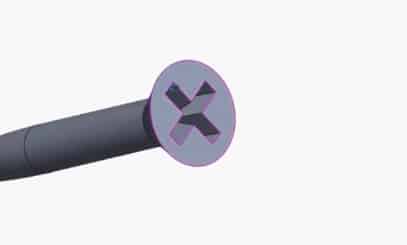
Then pick extruded cut from the feature menu. Enter a draft angle of 10 degrees and a depth of 2mm. The parameters can then be accepted by clicking the green checkbox. Then your t groove for the screwdriver will look somewhat like the one below.
Making the screw Thread
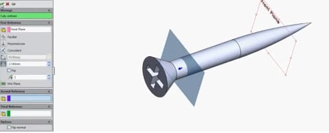
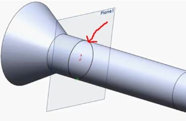
Go to the reference geometry, then pick the plane after selecting the front plane. As seen below, make an offset plane at a 17mm distance. To accept, click the green checkbox.
Right-click this plane now and choose Sketch. Select normal for the plane.
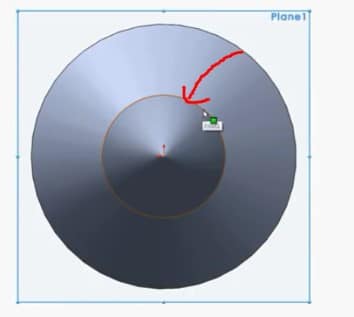
Next, choose “convert entities” while still selecting the circle that the red arrow is pointing at. You will then have a sketch of a circle.
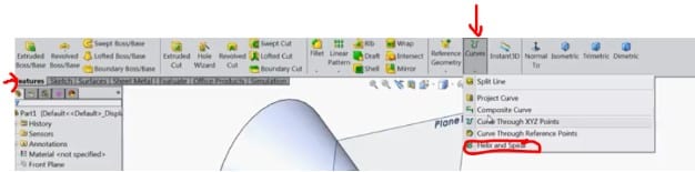
Exit the sketch mode. Next, choose Helix and Spiral from the Curves drop-down menu.
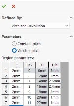
The manager for the spiral/helix tree appears. The Helix/Spiral tree manager appears. Put a 2mm pitch and 10 revolutions. Depending on your orientation, you may then select the reverse direction.
We may use variable pitch since the spiral is uniform throughout. Next, alter the pitch and revolutions until they are in line with the values in the table below.
Once you’ve done so, click the green tick to accept the settings. Right-click the selected top plane and choose Sketch. Click the normal to the plane.
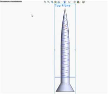
Then, using a line, sketch a triangle. Give it dimensions similar to those depicted in the drawing below.
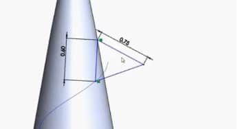
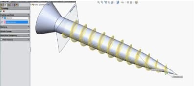
Make the other side equal to 0.75. Then press OK and exit from the sketch. Select Sweep Boss or Base, and select the triangle as the profile and the helix as the path.
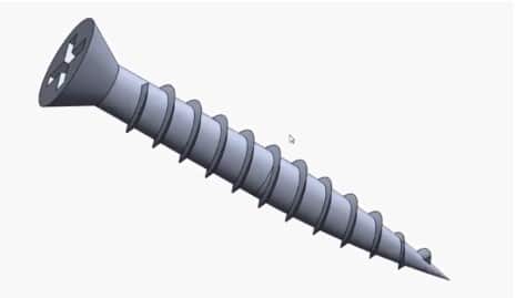
Next, click ok. The screw is now complete.