The SOLIDWORKS Combine function is a fantastic tool that is frequently used in surface modeling since it enables you to take molds of generated components for mold operations. You may use Combine in three distinct ways: to add, subtract, and find the area shared by two separate bodies.
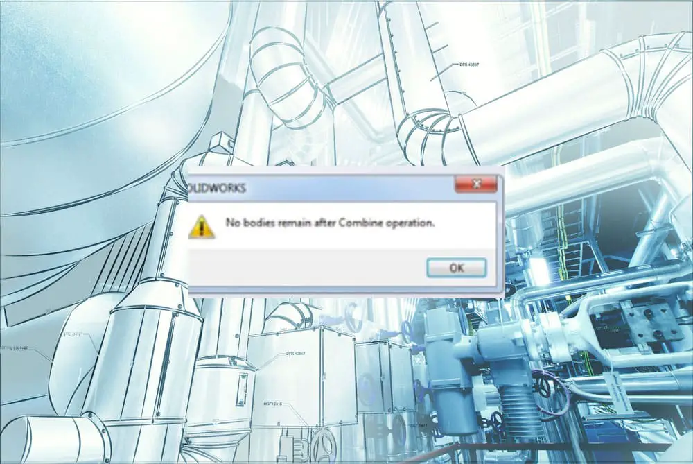
For this functionality, you will require a multi-body component. But the vast majority of customers who utilize the combine function frequently run into the problem that “no bodies remain after combine operation”.
In this post, I’ll describe how to troubleshoot “no bodies remain after combine operation.” I’ll also offer a few potential explanations for the error’s root cause. There will also be a presentation of a possible alternative for the combine approach.
Potential causes of the error
One of the primary causes of the combined operation failing is frequently due to a mistake in the SOLIDWORKS geometry that is preventing the feature from correctly finishing for whatever reason.
It may simply be a minimum radius that is lower than the offset value in the feature being utilized, or it might be a face or edge in the current geometry that is incorrect. The solids might not always be overlapping or sharing faces.
There are also circumstances where the solids do not share faces or overlap, which might be another cause of the “no bodies remain after combine operation” problem.
Resolving the Solidworks No Bodies Remain After Combine Problem
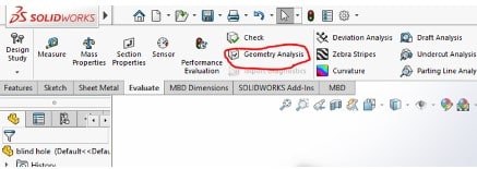
- Make use of the command “Check geometry”
The Check geometry command is a wonderful approach to identifying issues when things aren’t going so smoothly in the majority of cases.
So, use the Evaluate tab of Command Manager to test for geometry.
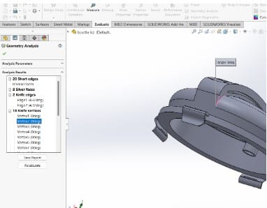
You may define the search parameters once you’ve chosen Geometry Analysis. Sharp Angles, Discontinuous Geometry, and Insignificant Geometry are the three basic categories under which these situations can be divided.
Short edges, tiny faces, sliver faces, knife edges, knife vertices, and discontinuous faces and edges are among the particular search criteria. Click Calculate once you have chosen your options and entered specific numbers for each criterion.
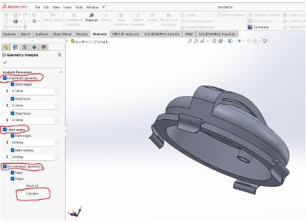
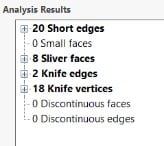
In this instance, Geometry Analysis discovered 20 short edges, 8 sliver faces, 2 knife edges, and 18 knife vertices. This does not necessarily imply that each of these occurrences needs to be resolved; rather, it only makes you aware of their existence so you may make a decision regarding how to address them.
Each condition is visible when the results are expanded in the PropertyManager; click on any of them to view where they are located in the model.
- Use the Encapsulation method
This technique takes far too long because it entails using the combine function more than twice, depending on the number of components in a single part file.
Making a larger solid that encloses (encapsulates) both of the sections that do not combine is another technique to address the “no bodies remain after combine operation” problem. Let’s assume that the two bodies are parts A and B that are not combining.
Make an enclosing solid volume that we may refer to as solid C. Subtract the two bodies (A and B) from the enclosing solid (C) volume in successive commands to generate a “negative” (Combine A and Combine B are subtract commands). To be able to look inside, you can keep the front face of the solid transparent.
Once more Construct an enclosing volume D that is bigger. Take the bigger volume D and subtract the smaller volume C (with the “negative”), keeping just the required body (Combine21 is a subtract command).
One body will be the end result of this. This body is basically what you would get if you combined parts A and B by adding them together.