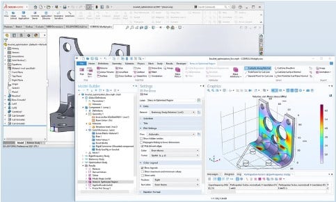
COMSOL Multiphysics is an excellent simulation program. Importing geometry from other software products, such as SolidWorks, necessitates the use of a specific license known as the CAD module, which requires a separate license. In this post, we’ll go through the process of importing a SolidWorks file into cosmol.
The Best Process to Import Solidworks Into Comsol
Basic configurations
When you choose your Solidworks file for import, you must define some basic options in the comsol import settings table.
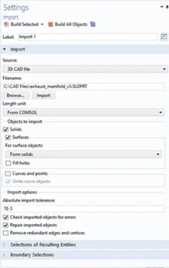
After importing a file, the program extracts data from the CAD files to identify the geometric entities in the file.
When the file is reimported as a result of a design modification, all of the choices made in COMSOL Multiphysics® will be updated and kept in accordance with associativity principles, preventing the need for further effort.
When importing CAD files stored in the native format of the software where they were generated, this information is often accessible.
Make a Geometry Repair on Import
A 3D CAD geometry can have tiny, hardly noticeable irregularities, despite the fact that it often accurately depicts the physical thing it represents.
This might be a result of numerical restrictions on the computer’s capacity to represent complicated forms, restrictions on some older CAD file formats, human mistakes, or data conversion issues.
As a result of these minute abnormalities, there can be irregularities in the face normals and edge directions, or faces that do not perfectly meet at the edges. Because of this, geometry correction is always carried out by default throughout the import process to help you get started with your simulations.
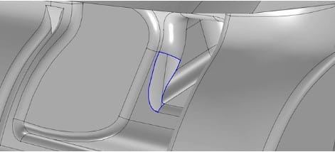
The CAD Import Module capabilities allow you to manually fix your CAD models after import in addition to the automated repair that takes place during import. For instance, you may manually choose faces and join them to build a solid using a predetermined tolerance to fill up gaps.
As an alternative, gaps may be automatically identified by their borders, which can then be used as input to create a new face that fills the hole and creates a solid.
Remove features from geometry for analysis (Defeaturing)
Due to the geometry’s complexity and the model’s abundance of small geometric characteristics, even after the CAD model has been correctly corrected, it could be challenging to employ in a simulation.
These characteristics might result in an excessively inflated number of mesh elements, using more computing resources than necessary, unless they are eliminated from the geometry before meshing. Tools to get rid of them and simplify the geometry are available in the CAD Import Module.
Fillets and chamfers can be removed, as well as groups of faces, which can then be filled or patched to create a homogeneous surface.
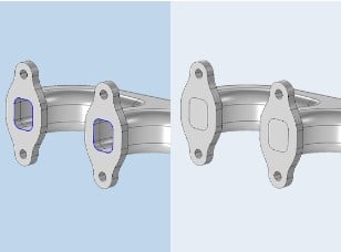
Close-up of a CAD geometry shown in a side-by-side comparison with and without capped faces.
Other undesirable characteristics, such as tiny faces, sliver faces, spikes, and short edges, can have been brought about by the CAD design and import procedure itself.
To identify and eliminate all instances of these accidental geometric features, you may define a tolerance value and its type in an interface. Defeaturing can be done automatically as part of the import procedure, using the same tolerances as for repairing.
Simplify the mesh by using virtual geometry operations
Similar to defeaturing, virtual geometry procedures leave the imported geometry unchanged. The virtual geometry procedures allow the mesher to disregard specific elements that either have little impact on the simulation or are not especially pertinent to the desired simulation, as opposed to altering the geometry.
After that, a virtual geometry is meshed. These operations include disregarding vertices, edges, and faces, creating composite edges and faces, collapsing edges and faces, and more. Virtual geometry procedures can be applied in two different ways.
The faces, edges, and vertices to be disregarded can be manually chosen, but there is also an automated Remove Details operation that detects and eliminates minor features by employing a series of virtual operations.
Additional Functionality Is Offered via LiveLink
COMSOL offers a plug-in that uses specialized LiveLink technology to link COMSOL Multiphysics with Solidworks. When modifications are made in one program, the synchronization mechanism in LiveLink products instantly updates the geometry in the other.
When using the LiveLink products, you may make modifications without having to import, export, and then reimport the full CAD geometry.