Thin features are quite obvious to you if you are familiar with SOLIDWORKS and have worked with CAD software in the past. Using thin features can help you make intricate cuts and shapes or even combine many stages into one.
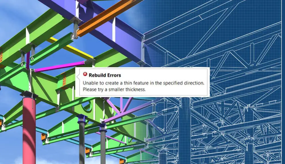
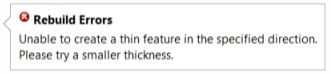
The majority of sketch-based features, such Boss Extrudes, spins, sweeps, etc., have the option of thin features. However, a lot of users of Solidworks get the error “Unable to create a thin feature in the specified direction” while utilizing the thin feature.
In this post, I’m going to discuss the sources of this error as well as remedies to the error notification.
What led to the problem?
Conflicting geometry in the creation of the thin feature is mostly to blame for the error’s existence. On the sketch, there can be pointed edges or small fillets that could cause the material to cross itself as you add thickness.
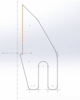
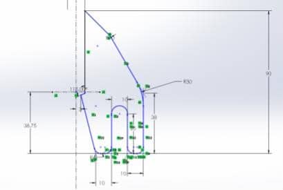
For instance, try a boss extrude of the profile illustrated below. Using a thickness of 7mm will cause the material between the profile sections to intersect, resulting in certain mathematical problems in the solver.
So I’m going to run the boss extrude command and select the thin option. I’ll go with a thickness of 7mm. Then I clicked the green check mark to run the command.
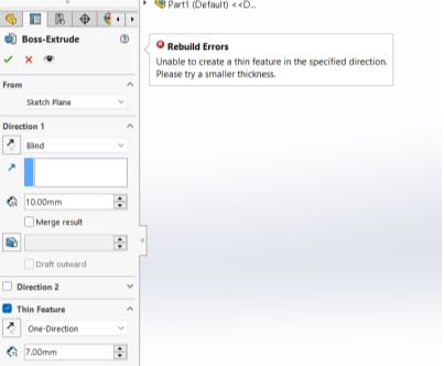
As a result, a rebuild error occurs, halting the entire operation.
Methods to Fix “Solidworks Unable to Create a Thin Feature in the Specified Direction” Error
Making changes to the feature drawing while it is being developed is one option. My drawing in this instance has a sharp vertex and tiny fillets.
I may just raise my fillet radii or vertex angles, or I can simply use a reduced thickness based on what the error is telling me to do. Therefore, we may apply the two techniques illustrated below to resolve our geometry concerns.
Method 1: Using the Check Sketch for Feature tool
Now let’s look at this geometry. A sketch that we made is what we want to extrude. Since it is a simple and well-defined drawing, everything could appear to be in order at first.
But as soon as we try to use the thin feature tool to build the Boss/Base-Extrude feature, we encounter this error.
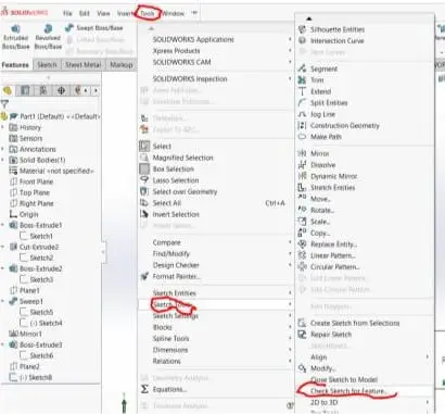
There is a tool called “check sketch for feature” that examines your drawing to determine whether it complies with the requirements for the feature you choose and will even enlarge any gaps to aid in their correction. It may be set up by selecting Tools > Sketch Tools > Check Sketch for Feature.
Choose the desired feature from the Feature Usage drop-down menu, then click Check.
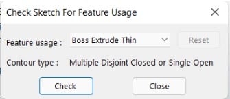
The results window will now inform you if you have open contours or not. If you do, click OK to proceed to the repair sketch phase. This is the point at which the tool magnifies the gaps and allows you to mend them. After correcting your sketch, you should be able to perform that feature with confidence.
Method 2: Employing trial and error
In cases where interference detection is ineffective, you will need to employ this strategy. Never leave out any crucial dimensions or relationships in a drawing. Though it’s not always required, working with completely developed drawings is the ideal approach.
You could mistakenly believe a line to be horizontal occasionally, but if there is no horizontal relationship to it, there is a chance that it is actually at a very small angle, like 0.001 degrees, which you can’t see by simply looking at it. So I’m going to play around with my thickness till I get a result.
NB: This technique may not be appropriate since it alters the object’s design requirements.