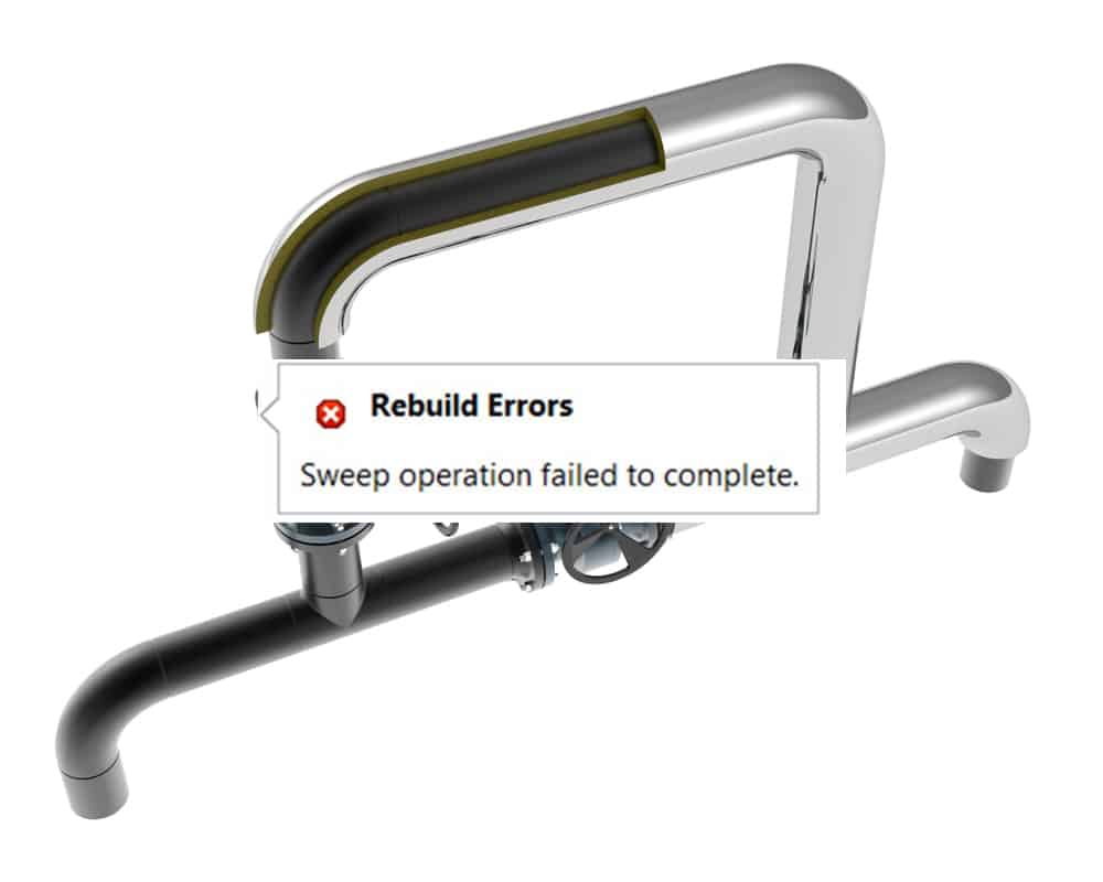
When trying to construct a sweep extrude or sweep cut feature in SolidWorks, the majority of users have encountered the terrible error message “Sweep Operation Failed To Complete”.

This is a very frequent issue that may be quite annoying, but fortunately, it is typically rather simple to diagnose and resolve. SolidWorks frequently provides you with quite excellent information about what’s wrong, which is one of its main advantages.
All you need to do is comprehend what the software is attempting to convey. Although it might be quite alluring to simply click error warnings away, it’s always worthwhile to study them and identify the issue.
In this instance, our error is trying to tell us three different things; we only need to determine which of these issues we’re actually dealing with.
Potential causes of the error
- The Sketch is self-intersecting
It is more formal to remark that some areas of your Sketch overlap. Single lines that are just joined at one end are likewise capable of being included.
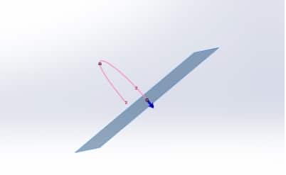
The image below demonstrates an example of “self-intersecting geometry”. When the sweep path is centered in the profile and a sharp sketch transition is added, the sweep p overlaps with itself.
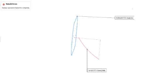
This mistake can also be caused by two lines being drawn side by side in the exact same spot. Use the Select Chain option to find these spots as they might be challenging to locate.
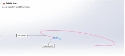
- Sweeping path and sketch planes on the same plane/parallel
The sweeping route and sketch planes cannot be on the same plane or parallel to one another. This is the fundamental rule for the sweep feature. If they do not follow this rule, an error will occur.
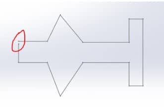
- Open sketch profile for a base or boss sweep feature
For a base or boss sweep feature, the profile must be closed; for a surface sweep feature, the profile can be either open or closed. This implies that the exterior of your profile cannot have any gaps or breaks.
How to Resolve the “Sweep Operation Failed to Complete” Error?
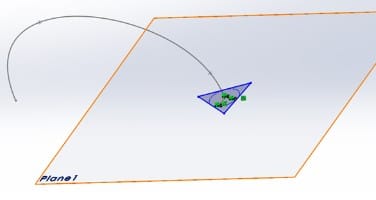
- The Sketch plane must be normal to the path at a point
At a certain location, create the sketch plane that is perpendicular to the path.
Create a sketch profile on that sketch plane that pierces the sketch path.
Sweeps that take a long time in Solidworks are either being combined with other solid bodies or the software is trying to anticipate what the final volume will look like.
Instead of attempting to deceive Solidworks into performing all of your work for you at once when creating anything complex, consider creating it one face at a time as surfaces. However, if you take the aforesaid actions, the outcome will be successful.
- Correct the geometry that self-intersects
In this scenario, I’ll utilize the figure shown above, which has this particular type of self-intersecting geometry. The sweep will function as intended after the self-intersecting geometry is resolved by shifting the path’s location.
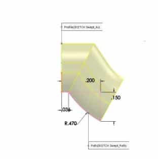
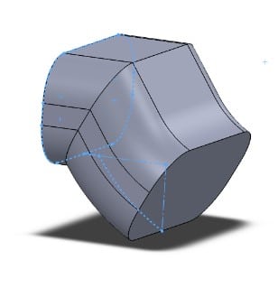
The path in the preceding example was altered such that the sweep path now pierces the bottom line rather than the profile’s center. One thing to bear in mind is that these modifications could deviate from your initial design objective. The finished product is seen below.
To repair the Open sketch profile for a base or boss sweep feature, just identify the opening and close the profile.
Sweep Tips
Sweeps must follow the following guidelines:
- For a base or boss sweep feature, the profile must be closed; for a surface sweep feature, the profile can be opened or closed.
- The path might be either open or closed.
- The path might be a collection of drawn curves enclosed within a single drawing, a curve, or a collection of model edges.
- The path must cross the profile’s plane.
- The section, path, and resultant solid cannot all be self-intersecting.
- The guiding curve must intersect the profile or a point in the profile drawing.
- You only use solid sweeps for cut sweeps, which are created by sliding a tool body down a path. The path must start at a location on or inside the tool body profile and be tangent within itself.
